4-bit Arithmetic Logic Unit in VHDL
A comprehensive 4-bit Arithmetic Logic Unit implemented in VHDL with 7-segment display integration.
Grade: 8.2
4-bit Arithmetic Logic Unit in VHDL
During my first semester at HAN University of Applied Sciences, I worked on an exciting digital circuits assignment: Developing a complete 4-bit Arithmetic Logic Unit (ALU) in VHDL. This project was part of the Digital Circuits 2 course and showcased the fundamental building blocks of computer processors. The project was successfully completed in collaboration with my teammate Len Verploegen.
Project Overview
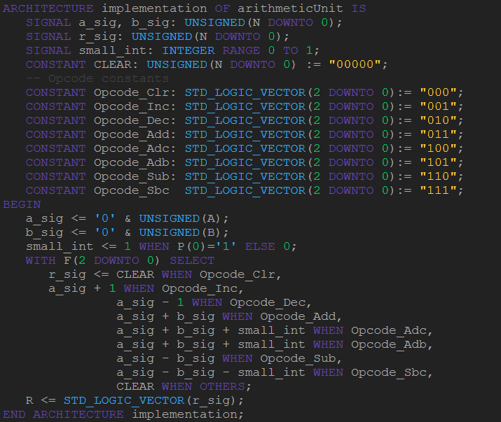
An Arithmetic Logic Unit is the computational heart of any microprocessor, capable of performing arithmetic operations, logical operations, and bit manipulation. Our ALU implementation supports 16 different operations through a 4-bit opcode system, with results displayed on 7-segment displays in both signed and unsigned modes.
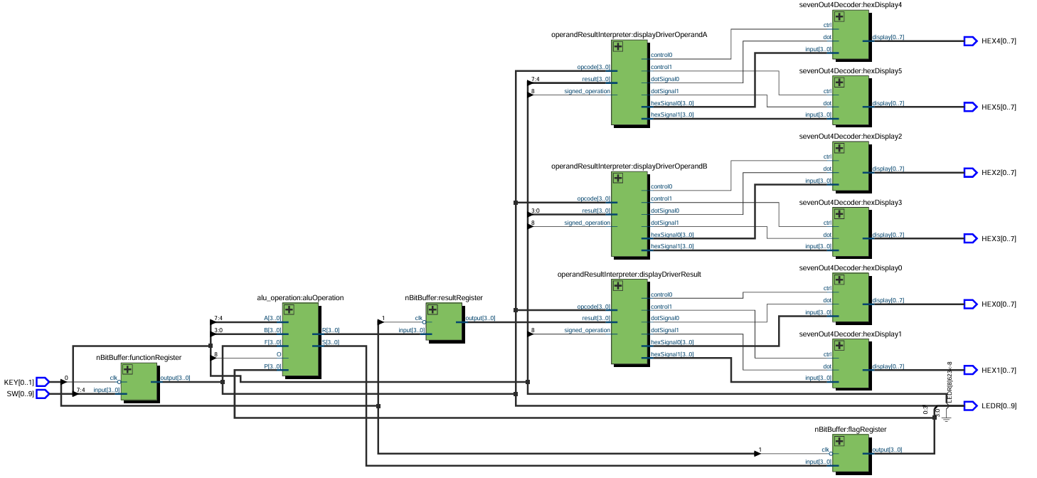
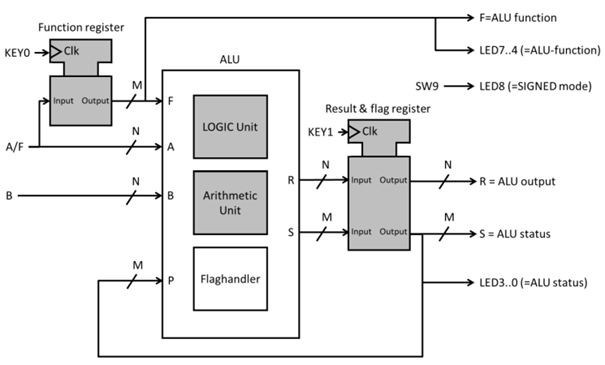
System Architecture
The system follows a modular design approach with several key components:
Core Components:
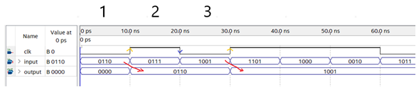
- n-bit Buffer: Configurable memory elements using D-flip-flops for storing operands
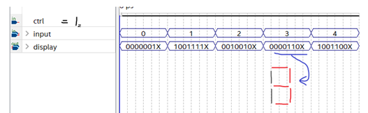
- 7-segment Decoder: Custom decoder supporting hexadecimal display (0-F) and extended characters for signed operations
- Arithmetic Unit: Handles mathematical operations (addition, subtraction, increment, decrement)
- Logic Unit: Performs bitwise operations (AND, OR, XOR, NOT, shifts, rotations)
- Result Interpreter: Manages display output and handles signed/unsigned representation
Features
- Comprehensive Operations: 16 different operations including arithmetic, logical, and bit manipulation
- Dual Display Modes: Both signed and unsigned number representation
- Real-time Feedback: Immediate visual feedback through 7-segment displays and LED indicators
- Flag System: Status flags for carry, overflow, zero, and sign detection
- BCD Support: Binary-Coded Decimal representation for specific operations
- Modular Design: Easily extensible architecture with configurable bit width
Technical Implementation
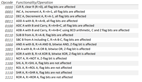
Supported Operations:
- Arithmetic: Clear, Increment, Decrement, Add, Add with Carry, Subtract, Subtract with Carry
- Logical: AND, OR, XOR, NOT, Shift Left/Right, Rotate Left/Right
- Special: BCD (Binary-Coded Decimal) operations
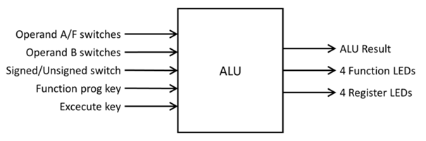
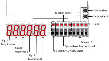
Input/Output Interface:
- 4-bit operand inputs (A and B)
- 4-bit opcode selection
- Function programming and execution buttons
- Hexadecimal display output
- LED indicators for flags and opcode status
Technologies Used
- Hardware Description Language: VHDL with NXP Freescale register-level programming
- Development Environment: Quartus Prime 19.1 IDE
- Target Platform: TerasIC DE10-Lite FPGA board
- Version Control: GitLab with TortoiseGit
- Documentation: Comprehensive testing and verification protocols
Key Technical Challenges
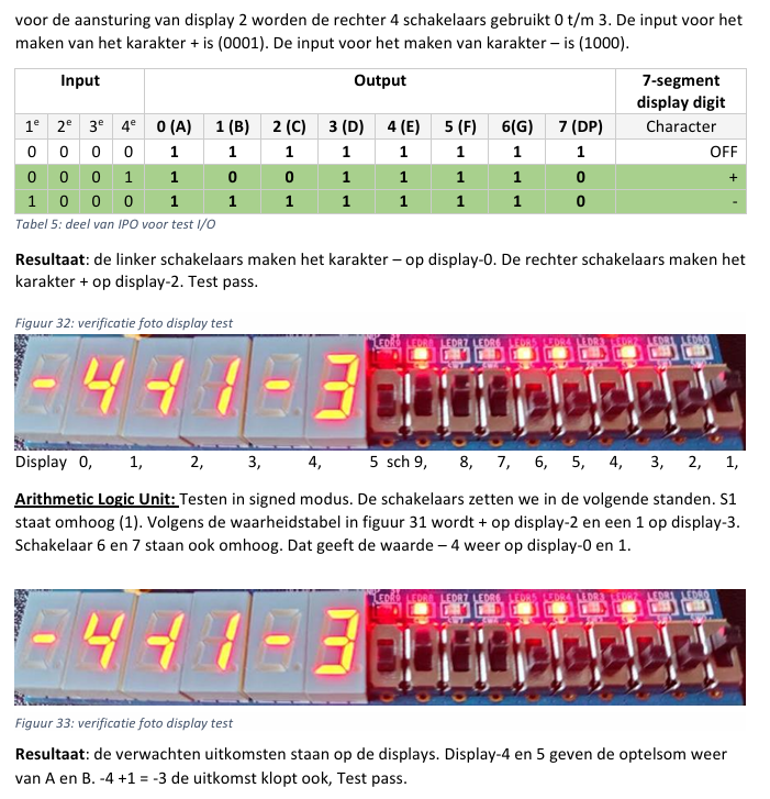
Signed Number Representation: One of the most interesting challenges was implementing proper signed number handling. We used two’s complement arithmetic combined with overflow detection to accurately represent negative numbers on the 7-segment displays.
BCD Implementation: The Binary-Coded Decimal feature required special handling to ensure proper decimal representation, especially for results exceeding single-digit values.
Modular Architecture: Designing the system with configurable bit width (using VHDL generics) ensures the design can be easily scaled for different requirements.
Development Process
The project followed the V-model development approach:
- Requirements Analysis: Defining all 16 operations and system specifications
- System Design: Creating architectural diagrams and component interfaces
- Implementation: Writing VHDL code for each component
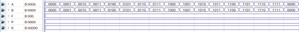
- Unit Testing: Individual component verification through waveform simulation
- Integration Testing: Full system validation on FPGA hardware
- Documentation: Comprehensive reporting and user manual creation
Results and Testing
Extensive testing was performed for all 16 operations in both signed and unsigned modes. The system successfully demonstrated:
- Accurate arithmetic calculations with proper carry and overflow detection
- Correct logical operations for all bitwise functions
- Proper display of results in hexadecimal format
- Reliable flag generation for system status indication
Project Reflection
This project provided invaluable hands-on experience with:
- Digital Design: Understanding fundamental processor components
- VHDL Programming: Mastering hardware description language concepts
- FPGA Development: Real-world implementation on programmable hardware
- Team Collaboration: Working effectively with project partners
- Documentation: Creating professional technical reports
The ALU project laid a solid foundation for understanding computer architecture and digital system design, skills that continue to be valuable in advanced embedded systems projects.
Future Enhancements
While the current implementation meets all requirements, potential improvements could include:
- Extended bit width for larger number processing
- Floating-point arithmetic support
- Advanced debugging features
- Integration with a simple processor core
This project was completed as part of the Digital Circuits VHDL (EMBHAC01-DIG2) course at HAN University of Applied Sciences, Embedded Systems Engineering program, S1 2021-2022.